

Centrifugal Compressor Working Principle: How It Operates Step by Step
2026-08-24
Ever wondered how massive industrial facilities manage to compress air to pressures that drive entire production lines? The answer lies in the centrifugal compressor, a machine whose working principle is both elegant and powerful. In this step-by-step guide, we’ll break down exactly how it operates—from the impeller’s acceleration to the diffuser’s pressure recovery. Whether you’re an engineer or simply curious about the tech behind modern manufacturing, this post will give you a clear picture. And if you’re looking for reliable compressed air solutions, Seize Air has you covered.
Why inlet conditions shape the compression curve before the impeller moves
Before the impeller starts to rotate, the velocity distribution and total pressure profile in the inlet duct have already decided how flow approaches the leading edges. A thick hub-side boundary layer or a swirling component from an upstream bend alters the local incidence angle at each blade station, so the relative velocity triangle is partially fixed even at zero rotational speed. These spatial non-uniformities translate directly into where the compressor will encounter stall or choke on its characteristic map.
Total pressure distortion and wake shedding from struts or probes produce a circumferentially varying incidence pattern that persists once the blades begin moving. The resulting periodic loading imbalance does not average out in the early part of the compression curve; instead, it shifts the onset of instability toward a higher flow coefficient. Low-momentum fluid accumulating near the shroud also limits the diffusion that the blade row can achieve, which is why the pressure ratio knee appears earlier than an ideal one-dimensional prediction would suggest.
Even the static Mach number distribution measured at the impeller eye before rotation carries a signature of the loss regions that will dominate later. Reverse flow pockets or tip clearance vortices seeded by inlet geometry do not need impeller motion to begin shaping the downstream static pressure field. The compression curve therefore inherits these inlet asymmetries, and the steep drop at low flow is often a replay of conditions that were already present in the inlet annulus before the first revolution.
How the impeller blades transfer velocity energy to the gas stream
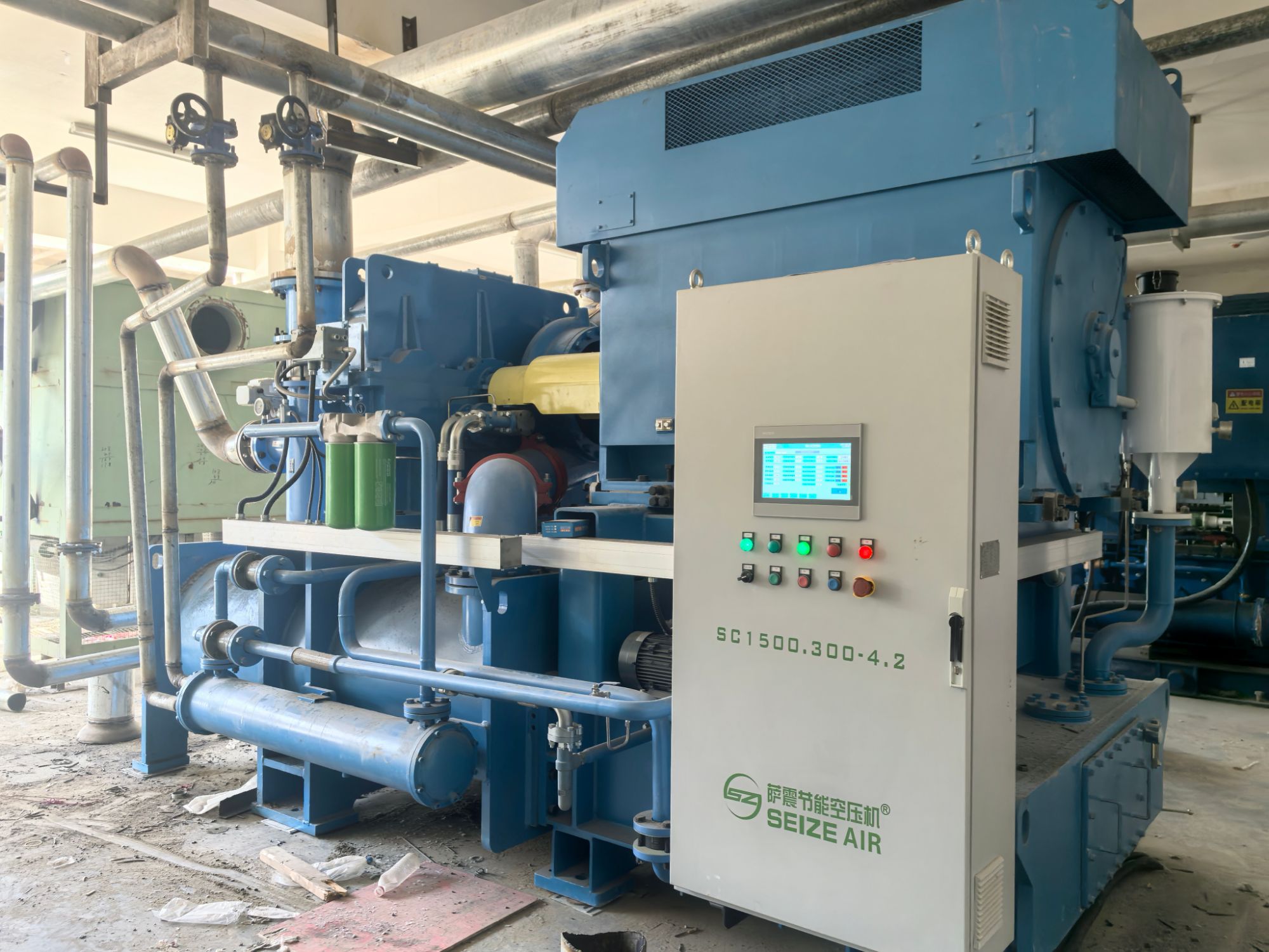
As the impeller spins, each blade sweeps through the gas like a curved paddle pushing against a fluid. The gas trapped between consecutive blades gets dragged along the rotational path, and because the blades angle backward relative to the direction of rotation, they continuously accelerate the gas outward. This forced movement converts the mechanical work of the shaft directly into kinetic energy, raising the velocity of the gas far beyond what it had at the inlet.
The velocity isn’t just a straight-line speed; it’s a combination of the tangential push from the blade and the outward radial flow caused by centrifugal force. The gas leaves the blade tips with a substantial tangential component, which is the key stored velocity energy. Think of it as the gas being flung off the edge of a spinning disk—by the time it departs the impeller, it carries a high-speed swirl that later gets harvested.
This swirling motion enters the diffuser, where the flow path widens. As the gas slows down within the expanding passage, that velocity energy transforms into pressure. The blades don’t just move the gas; they give it a purposeful high-speed spin that the downstream components then convert into the static pressure rise needed for compression or ventilation.
What the diffuser does to convert high-speed flow into usable pressure
At its core, a diffuser is a duct that widens gradually in the direction of flow, forcing the incoming high-speed stream to slow down. As the flow decelerates, kinetic energy drops and static pressure rises—this is the classic Bernoulli trade-off, but with real-world losses. The key is managing the adverse pressure gradient: too steep a widening and the boundary layer separates, creating turbulence and backflow that waste the pressure recovery you're after.
In practice, good diffuser design walks a tightrope between ideal pressure recovery and stall. Angles between 5 and 10 degrees on each wall typically keep the flow attached, allowing a smooth conversion of velocity head into pressure head. Vaned or splitter designs push this further by subdividing the flow path, preventing the low-energy fluid near the walls from reversing. The result is a higher usable static pressure at the outlet—crucial for feeding combustors in gas turbines or reducing velocity before a filter or heat exchanger.
What separates an average diffuser from an excellent one is how uniformly the pressure rises across the outlet plane. Non-uniform recovery leads to distorted downstream flow, which can rob an entire system of efficiency. By shaping the diffuser contour—sometimes using curved or trumpet-like profiles—engineers coax the flow to decelerate evenly, converting as much as 85–90% of the theoretical dynamic pressure into static pressure. That recovered pressure is what drives combustion, ventilation, or process flow, making the diffuser a silent workhorse in fluid systems.
Where the volute casing directs the swirling discharge without pressure loss
The volute casing takes the high-speed, swirling flow thrown off the impeller and eases it into a single outlet stream. Its spiral channel widens gradually, letting the fluid slow down while the pressure builds back up. Because the cross-section grows at a rate matched to the flow, the conversion from kinetic to pressure energy happens smoothly, and the fluid never slams into a sudden wall or dead zone. That is what keeps the pressure loss remarkably low compared to a straight collector ring.
A closer look at the tongue, or cutwater, shows how critical that small gap really is. It splits the flow right at the discharge, sending most of it out while a tiny portion recirculates with the impeller. If the tongue is too close, you get vibration and erosion; too far, and leakage swirls back and steals energy. The cross-sectional shape also matters—a rounded, slightly flattened profile reduces secondary flows better than a simple rectangular duct, so the swirling discharge lines up with the outlet without creating sharp vortices.
What makes this worth paying attention to is how the volute avoids the bulky diffuser vanes often used in multistage pumps. Instead of a ring of stationary blades that add cost and clogging risk, the casing itself does the work. The swirl from the impeller is not fought against but redirected, preserving nearly all the head the impeller produced. In well-designed units, the pressure recovery through the volute can exceed eighty percent of the theoretical maximum, which is why this simple spiral remains the default choice for single-stage centrifugal pumps.
When intercooling between stages keeps thermal load from cutting efficiency
In multistage compression systems, the temperature rise between stages can quietly erode overall efficiency if left unchecked. By placing an intercooler after the first stage, the gas is brought back down to a temperature closer to ambient before entering the next compression stage. This drop in temperature directly reduces the thermal load on the second stage, meaning less work is needed to achieve the same pressure ratio—and the machine doesn't have to fight against its own heat buildup.
The real payoff shows up in the compressor map and the energy bill. Without intercooling, the second stage would have to handle a hotter inlet charge, pushing it into a region where specific volume expands and adiabatic efficiency drops. With an intercooler in place, the second stage sees a denser, cooler mixture, allowing it to operate closer to its designed sweet spot. The result is a smaller drop in isentropic efficiency and a measurable cut in power consumption per unit of compressed gas.
Field experience often points to a threshold where the intercooler stops being a nice-to-have and becomes a must-have—usually when the overall compression ratio climbs above roughly four to one. Below that, a single stage with good cooling jackets may suffice. Above it, the thermal load on the downstream stage begins to cut into efficiency so sharply that the intercooler pays for itself in lower operating costs and reduced wear on valve plates and seals. Engineers who skip this step often find themselves derating the compressor to keep discharge temperatures under control, which defeats the purpose of high-pressure delivery in the first place.
How seals and bearings hold the rotor steady under varying load
A rotor rarely sees a constant push. Load shifts as flow demand changes or as process fluid density fluctuates, and that can shove the shaft off its ideal centerline if the support system lacks any “give.” Bearings take the brunt of this work by forming a thin, pressurized film—either from oil, grease, or the process fluid itself—that resists sudden radial movement without locking the shaft in place. That film thickness changes with load, but the bearing geometry and feed pressure automatically adjust the wedge shape to keep the rotor’s orbit small. Seals, often overlooked as just leak stoppers, add a second layer of control: their close clearances and pressure breakdown across each tooth or face generate a restoring force that counteracts the same side loads.
In practice, a tilting-pad or sleeve bearing will shift its pads slightly under increased load, which reduces the oil film thickness on the loaded side and increases it on the opposite side. This asymmetric squeeze creates a hydrodynamic pressure spike that pushes back, letting the rotor settle into a new but still-centered position. The seal complement works in tandem. A labyrinth or honeycomb seal, for example, breaks down pressure in stages; as the shaft moves closer to one side under load, the local clearance there shrinks, which raises the gas or liquid pressure in that pocket and forces the shaft back. That is why seal clearance and bearing preload are often selected together: one sets the allowable orbit, the other supplies the damping to keep it from growing.
What matters most is not a single component’s strength but the combined stiffness and damping curve across the operating range. When a machine swings from cold start to hot full load, both bearing clearances and seal gaps change with thermal growth. A well-matched pair will keep the rotor’s first critical speed safely away from running speed even at maximum unbalance. Field tuning often means swapping seal rings or adjusting bearing oil flow to shift that curve, rather than simply tightening everything down. The steady rotor is less a matter of brute clamping than of giving the system just enough controlled leakage and film resistance to absorb load variation without letting the shaft wander.
FAQ
Gas gets pulled into the eye of the impeller, and as the impeller spins, the blades throw it outward. This rapid outward push increases the gas velocity dramatically, and then the shape of the surrounding passage slows it down, converting that speed into higher static pressure.
The impeller's curved blades are designed to continuously accelerate gas in a radial direction. Unlike positive displacement machines that trap fixed volumes, a centrifugal compressor relies on dynamic energy transfer, which suits high-flow applications where continuous movement matters more than trapping gas.
It comes from two places. A portion comes from the centrifugal force acting on the gas as it moves outward, and the rest comes from the diffuser, where the gas slows and its kinetic energy converts into pressure. Without the diffuser, much of that velocity would be wasted.
Once the gas leaves the impeller tip at high speed, it enters the diffuser, which is a ring of narrowing or vaned passages. The increasing cross-sectional area forces the gas to decelerate, and that deceleration translates directly into a pressure boost before the gas moves on.
The volute collects gas from the diffuser and guides it toward the discharge nozzle. Its gradually expanding cross-section further reduces gas velocity and adds another small pressure increase, while also evening out the flow so it exits smoothly rather than in pulses.
The gas is routed into a second stage, where another impeller and diffuser repeat the process. Between stages, the gas may pass through an intercooler to remove heat from compression, which reduces the work required in the next stage and prevents excessive temperatures.
If the compressor has variable inlet guide vanes, they adjust the angle at which gas approaches the impeller. Changing this angle alters the gas velocity triangle and thus the flow rate and pressure ratio, letting the compressor operate efficiently across a wider range without changing impeller speed.
Because compressing gas means doing work on it, and not all of that energy goes into raising pressure. Some becomes heat due to friction and the inherent thermodynamic effect of reducing volume while increasing kinetic energy. The temperature rise is why many systems need aftercoolers or intercoolers.
Conclusion
Before a centrifugal compressor's impeller ever moves, the inlet duct geometry, temperature, and pressure establish the gas density and approach angle that dictate where the performance curve begins. A slight swirl or uneven flow at the eye can reshape the entire map before the first row of blades adds work. Once the impeller rotates, its curved vanes fling the gas outward, converting mechanical shaft power into velocity energy; the gas leaves the blade tips at high speed. Directly downstream, a vaneless or vaned diffuser gradually widens the flow area, slowing the stream and trading that kinetic energy for static pressure. Rather than dumping the now-swirling discharge into a sharp turn, the volute casing spirals around the wheel, collecting the flow with a constant or gently increasing cross-section so the high-pressure gas reaches the discharge nozzle without unnecessary friction or separation losses.
In larger multistage machines, gas heated by compression moves to an intercooler between stages. Removing that heat before the next wheel reduces the volume flow and brings the compression path closer to isothermal, which cuts power demand and prevents excessive temperatures from eroding efficiency. All through this process, the rotor must stay centered while aerodynamic and mechanical forces change with load. Labyrinth or dry gas seals minimize internal leakage along the shaft, while oil-film or magnetic bearings absorb thrust and radial movement, keeping clearances tight enough for stable operation across a range of flows.
Contact Us
Contact Person: Mia
Email: [email protected]
Tel/WhatsApp: +86 19821985894
Website: https://www.seize-air.com