
Roller Hearth Furnace Fundamentals Every Engineer Should Know
2026-08-16
Roller hearth furnaces quietly power some of the most demanding heat-treatment lines in modern manufacturing—yet their core principles often get buried under jargon and vendor specs. This guide strips the subject back to what actually matters: how the rollers, atmosphere control, and temperature uniformity interact in ways that can make or break your process. Whether you're troubleshooting a recurring hot spot or designing a new line from scratch, the insights here come from field-hardened experience rather than textbook theory. For deeper engineering support on thermal systems, visit THINKING-LONG and see how practical expertise translates into furnace performance.
Roller Material Selection Often Comes Down to Thermal Shock Resistance
Roller materials often fail not because of steady-state operating temperatures but because of rapid temperature swings. A roll that handles hot strip one moment and cold strip the next must endure repeated expansion and contraction. Under such thermal cycling, materials with poor thermal shock resistance develop surface cracks that grow with each cycle. These cracks eventually lead to spalling, reduced roll life, and unexpected downtime. In many mills, the selection process starts by quantifying the temperature differential the roll will see in service. A material that can flex with those temperature changes without cracking at the grain boundaries tends to outlast one that simply has a higher melting point.
Ceramic rollers, for instance, often excel in high-temperature stability but may shatter when subjected to sudden cooling. Conversely, some high-alloy steels absorb thermal gradients more gracefully due to their ductility, yet they sacrifice hardness. The real challenge is balancing thermal shock resistance with wear resistance and compressive strength. Engineers sometimes look at parameters like the thermal shock parameter R, which combines thermal conductivity, tensile strength, and elastic modulus to predict a material's tolerance. But numbers alone don't tell the whole story—field performance under specific quench conditions and roll rotation speeds often reveals which material truly handles the heat.
The Quiet Cost of Wide Roller Spacing on Temperature Uniformity
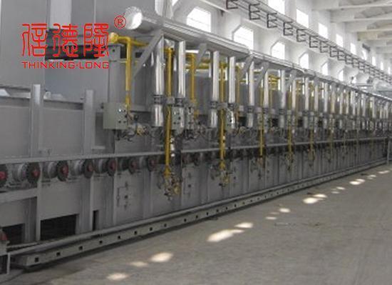
Wide roller spacing quietly undermines temperature uniformity in ways that rarely show up on a standard spec sheet. When rollers sit far apart, the material between them loses consistent contact with the heated or cooled surface, creating micro-zones where heat transfer drops off. These bands may go unnoticed during quick inspections, but they leave a fingerprint in the form of uneven curing, slight viscosity shifts, or subtle gloss variation across the web.
Operators often chase the symptom rather than the spacing. They adjust zone temperatures, tinker with line speed, or add post-process correction, yet the root cause remains mechanical. A narrower roller pitch, even by a few millimetres, restores more uniform support and reduces the thermal bridging gaps that cause edge-to-centre drift. The fix is not glamorous, but it is repeatable.
The real cost appears later: rejected batches, higher energy draw to compensate for cold spots, and accelerated wear on downstream components that must handle inconsistent material stiffness. Teams that measure surface temperature profiles across the full width, rather than relying on a single point, are the ones who catch wide spacing before it becomes a chronic yield problem.
Atmosphere Control Goes Deeper Than Just Nitrogen Versus Hydrogen
Many line engineers still frame atmosphere selection as a binary choice between nitrogen and hydrogen, but that mindset overlooks what actually happens at the metal surface. The real variables are dew point, oxygen partial pressure, and the local flow pattern around the parts. A furnace can be fed 95% nitrogen and 5% hydrogen and still produce oxidized or discolored work if the incoming gas carries just a few parts per million of water vapor, because that moisture shifts the oxidation-reduction equilibrium at temperature. Even small variations in the ratio between the gas inlet and the exhaust can create stagnant pockets where the protective atmosphere never reaches the load.
Beyond composition, atmosphere control means managing how the gas moves and reacts as the temperature changes. In continuous furnaces, the same gas blend must behave differently in the preheat zone, the high-heat zone, and the cooling section. A blend that prevents decarburization at 800°C might be too aggressive at 1100°C, or too sluggish to reduce oxides during rapid cooling. Practical systems use oxygen probes and dew-point sensors not just to confirm the setpoint, but to trim the flow in real time. The goal is not a static “good” mixture, but a dynamic envelope that follows the thermal profile and the actual surface condition of the workload.
Gas purity and delivery hardware matter as much as the nitrogen-to-hydrogen ratio. A well-mixed, high-purity feed can be ruined by a leaking flange, moisture trapped in refractory, or a regulator that introduces a dead volume of air during cylinder changeover. Atmosphere quality also depends on whether the gas sweeps the chamber uniformly or channels along the walls, leaving the center of the load under-protected. These are the kinds of details that separate a robust process from one that only looks correct on the flow meter.
Why Your Loading Pattern Changes Effective Furnace Capacity
The moment a furnace is loaded, the relationship between part placement, spacing, and airflow shifts. Operators often assume a fixed chamber volume equals a consistent processing capacity, yet real throughput depends on how heat actually reaches each component. Tightly packed loads can starve the center of the batch, while excessive gaps waste energy and slow cycle times. Understanding this dynamic means recognizing that effective capacity is not a static number—it is shaped by every rack, basket, and orientation choice.
Different loading patterns create invisible hot and cold zones that alter soak times and final hardness. For example, stacking dense parts vertically may block convection from reaching mid-level layers, forcing the furnace to hold temperature longer just to bring lagging areas up to spec. Conversely, deliberately staggering small parts or using hollow spacers can break up stagnant flow, letting the same chamber process more work per hour without raising setpoints. This is why the same furnace can deliver drastically different output on paper versus in practice.
A strategic loading pattern treats the workload as part of the thermal system, not just an occupant of it. Shifting from flat trays to angled supports, varying part orientation between rows, or even mixing part sizes within a load can redistribute airflow and radiation more evenly. Over time, these micro-adjustments reduce rework, shorten cycle windows, and unlock capacity that a conventional “fill the chamber” mindset leaves on the table. The result is a furnace that runs closer to its true potential—without adding a single square foot of floor space.
Drive Slippage Can Show Up as Product Quality Drift
When a belt, chain, or roller drive begins to slip, the immediate symptom is often just a slight loss of speed or torque. Over time, that small inconsistency transfers directly into the production line. For example, a conveyor that hesitates for a fraction of a second per cycle can alter coating thickness, placement accuracy, or curing time. The result is a gradual shift in finished goods that may still pass individual checks but fail final tolerances.
This drift is easy to misdiagnose because the raw materials and machine settings haven't changed. Operators see the same recipe, the same temperatures, and the same feedback from sensors that only monitor the motor output, not the actual surface speed. The slip happens at the interface—between pulley and belt, or wheel and rail—so upstream signals look normal. Quality data, however, starts trending toward the edge of control charts. Dimensions, weights, or surface finishes begin to wander even though no alarm sounds.
Catching drive slippage early requires looking past the dashboard and measuring what reaches the product. Handheld tachometers, high-speed cameras, or simple chalk marks on rotating shafts can reveal a mismatch between commanded and actual motion. Once slippage is confirmed, tightening tension, replacing worn friction surfaces, or adjusting load distribution usually brings product quality back in line. The fix is often mechanical and inexpensive compared to the scrap and rework caused by unexplained drift.
The Furnace Shell Usually Leaks More Heat Than the Exhaust Stack
Industrial furnaces lose heat through several paths, but the shell often accounts for the largest share. Exhaust gases carry energy away at high temperatures, yet their flow is concentrated and relatively easy to capture or insulate. The shell, by contrast, is a large continuous surface exposed to the surrounding air. Even with refractory lining, gradual wear, thermal cycling, and imperfect seals create countless points where heat escapes. Over weeks and months, these small losses add up faster than the dramatic but intermittent exhaust plume.
Maintenance teams sometimes focus on stack temperatures because they are visible and easy to measure. But infrared scans frequently show hot spots all over the furnace body, especially around doors, expansion joints, and older brickwork. Those areas radiate heat around the clock, regardless of whether the furnace is running at full load or idling. A stack can be tuned or fitted with a heat recovery system, but shell losses require a different approach: better insulation, tighter gaskets, and regular inspection of the entire envelope. Ignoring them means paying for fuel that never reaches the product.
In many plants, the difference becomes clear when comparing two furnaces of similar age and duty. The one with a well-maintained shell but a hotter stack often uses less total energy than the one with a cool stack and a leaking shell. That inversion surprises people who assume exhaust dominates all heat loss. The practical lesson is to measure surface temperatures across the full shell, not just the stack, before deciding where to invest in energy-saving upgrades.
FAQ
Many assume a uniform setpoint automatically means uniform heating, but radiation view factors along the furnace length and heat transfer through the rolls can create noticeable temperature differences across wide workpieces.
Choosing the wrong roll alloy leads to high-temperature creep, oxide buildup, or surface pitting, which causes product wandering and jams; the resulting unplanned maintenance often costs more than the rolls themselves.
Continuous charging and discharging keeps the furnace openings interacting with outside air, so a small drop in positive pressure or a faulty seal curtain can quickly shift dew point and oxygen levels inside.
If rolls are spaced too far apart, bars or tubes sag between them, increasing local contact time and distortion; too close a pitch adds heat loss and drives up the total drive load.
For extremely heavy loads, scratch-sensitive surfaces, or tight product packing, a walking beam avoids roll contact issues; roller hearths work better for long products needing fast, continuous processing.
Common approaches include flexible couplings, floating bearing housings, or segmented drives that let each roll grow axially without transmitting stress to gearboxes and support frames.
Hot spots on the shell, unstable furnace pressure, flames around roll necks, and discolored support steel usually appear well before major lining spalling becomes visible.
Improper cooling rates create residual stress, uneven oxide colors, and thermal shock cracking in rolls, all of which undermine downstream processing and final product quality.
Conclusion
Roller hearth furnaces demand attention to details that rarely appear in spec sheets. The choice of roll material, for instance, often hinges less on high-temperature strength and more on thermal shock resistance—cracks from rapid heating or cooling cycles cause far more failures than gradual wear. Even with durable rolls, their spacing quietly influences the product: wider gaps between rolls let heat escape unevenly across the strip or slab, creating cold bands that degrade temperature uniformity. Atmosphere control is another area where oversimplification hurts. Engineers tend to debate nitrogen versus hydrogen, but the real challenge lies in maintaining consistent dew point, flow distribution, and tight sealing—because a well-mixed reducing atmosphere can still fail if moisture or oxygen sneaks in near the charge end.
Operational habits also reshape what a furnace can actually do. Loading patterns that look efficient on paper may block radiant heat from reaching the center of the load, effectively shrinking the furnace's useful capacity below its nameplate rating. Drive slippage is a subtler problem: rollers that slip slightly under heavy or uneven loads produce variable residence time, and that drift shows up as inconsistent hardness or grain size in the final product. Finally, while exhaust stacks get most of the attention in energy audits, the furnace shell itself usually leaks more heat through worn insulation, gaps around roll openings, and poorly sealed doors. Fixing those quiet losses often yields faster payback than upgrading burners or controls.
Contact Us
Contact Person: Qian Xijun
Email: [email protected]
Tel/WhatsApp: 8613961736750
Website: https://www.thinkinglong.com/